Operation Diagrams
The following stick diagrams outline some suggested applications for the BeerBotz system. These diagrams
depict the sensor and relay connections that can be made to the BeerBotz interface for each use-case.
Monitor Mash Temperatures
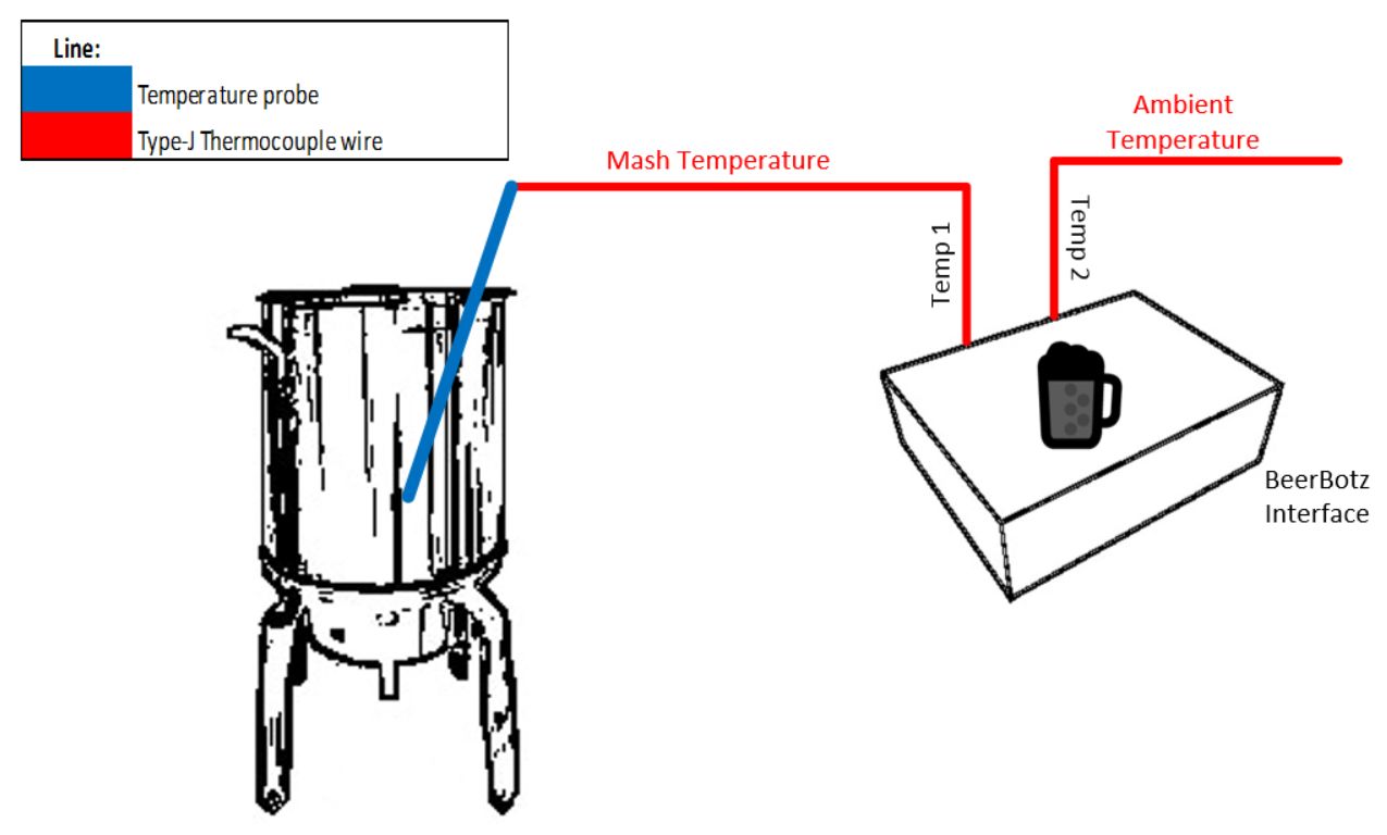
This is the easiest one to set up, so it should probably be the first one you try. Temperature one
(Temp 1) is connected to a probe that is measuring the mash temperatures. The Temp 2 thermocouple
is just left dangling to measure the room temperature.
In the software, Temp 1 and Temp 2 are enabled in the "Acquisition" page. Once started, you can view
all of the incoming data in the "Aquisition" page. Go to the Main page for a larger numerical view
of the changing mash temperature. You can double-click this number to change it to full screen
(and double-click to get back from full screen). With the mash temperature at full screen, you can
see the temperatures from across the room.
Next, set up the software to save the rows out to Excel™. This is done by checking the
"Save to Excel?" box next to where you specified the particular spreadsheet you are using. You need
to stop acquisition to make this change. For this excercise, specify (in the "Acquisition" tab)
Samples/minute = 60, and Samples to Combine = 20. This setting gives you a row of data written to
Excel™ every 20 seconds. In the "Storage" tab check the "Auto Update Graph" button.
This will cause the chart in Excel™ (on sheet 2) to refresh every time a new row of
data is written into sheet 1. Now re-start the aquisition and, as the mash data is changing, display
the Excel™ chart. You will see the graph build as the the new data compiles. This graph
shows the rate/angle that the mash is heating up at, so it can be roughly determined when then next
mash target temperature will be reached.
Monitor Gas - Control Freezer Temperature
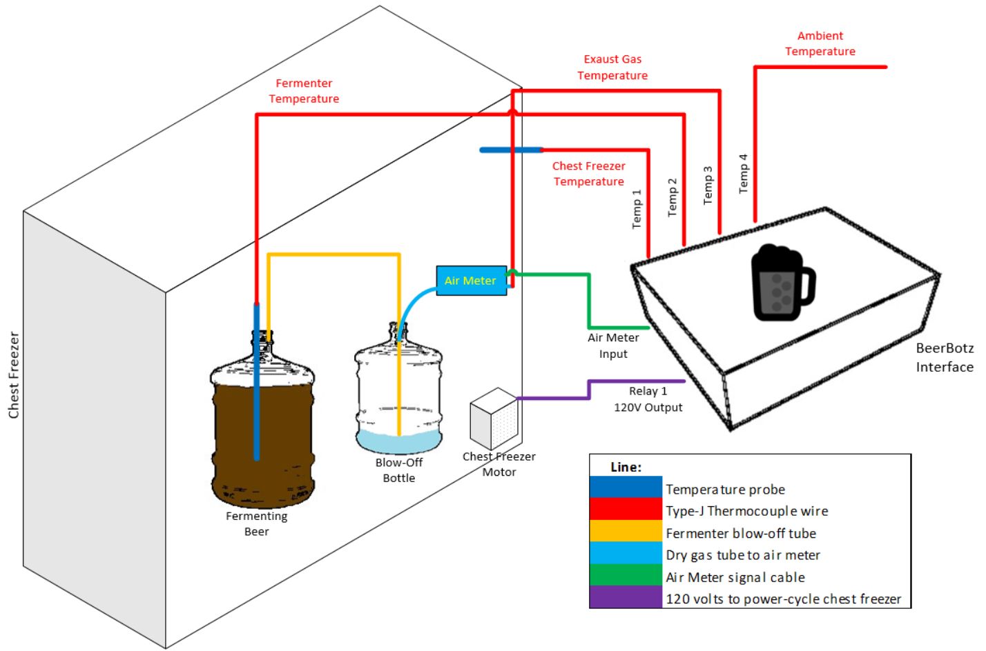
This one uses all of the connection types available on the BeerBotz interface. The tempertures of the
fermenter and the inside of the chest freezer are measured. The chest freezer motor/compressor is
switched on/off by the Relay 1 output. And finally, the air meter input is connected to the a gas
sensor on the outlet of the fermenter.
Temp 1 monitors the inside temperature of the chest freezer. Relay 1 (when activated) keys off of the
numerical values from Temp 1, depending on the user-defined setpoint. The Relays are separately activated
in the "Relay Outputs" tab. The interior temperature of the chest freezer is maintained at the desired
temperature by Relay 1 power-cycling the freezer conmpressor.
Temp 2 is taking the temperature from a probe inside the active fermenter. Temp 3 is the temperature of
the gas that is being exhausted from the gas flow sensor. This temperature would be necessary to know if
one wanted to convert from volumetric flow to mass-flow and visa versa. Knowing the mass flow is what is
desired to calculate the sugar consumption (specific gravity), and the ethanol production. The Honeywell™ AWM series
meters read directly in mass flow, so this exhaust-gas temperature is not really
needed.
Temp 4 is just a dangling thermocouple wire for the room temperature again.
The Air Meter is connected to the Air Meter Input. There are three of this type of input, so you can
watch three fermentations simultaneously. These inputs are designed to work with the Honeywell™
AWM series meters. The cable from the BeerBotz interface both provides the power to the air meter, and receives
the signal from it. The AWM series meters output one volt at zero gas flow, and five volts at the top
range of the meter. In the Acquisition tab, you can choose to output this gas meter voltage directly,
or you can apply a "calibration table" that will output the values directly as grams of CO2
/minute.
Finally, the power for the chest freezer motor/compressor is connected to the BeerzBotz Relay 1 output.
This output will turn on the 120 volts power to the freezer when necessary. The temperature setpoint
and hysteresis (+/- value) for the inside of the freezer is configured in the Relay Outputs tab. Again,
Relay 1 always keys off of the Temp 1 values. The Relays timer is started seperately from the data
acquisition. Data acquisition must be "Started" before the relays timer will start, ie, there must be
new data coming in for the relays timer to look at.
The relays timer checks to see if the power should be turned "on" at a user-defined time interval. Thus,
if the relays timer is set to ten minutes, the freezer compressor will never turn "on" more than once
every ten minutes. This is necessary because power cycling the freezer often decreases the life of
the compressor. Once the freezer has been turned "on", the BeerBotz checks for the setpoint temperature
to be reached once every second. Once reached, the power to the freezer is turned "off".
The hysteresis value is used in conjunction with the temperature setpoint to determine when the freezer
gets turned "on". If the setpoint is 50F with a hysteresis of 3, the freezer will not turn on until the
inside of the freezer is greater than 53F. The power will then stay on to the compressor until the
freezer temperature reaches a value of lower than 50F.
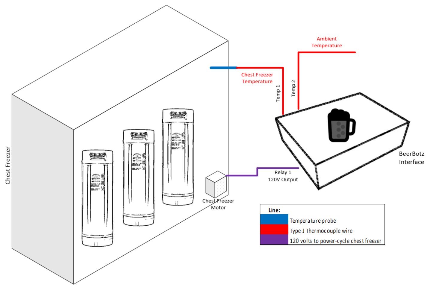
Control Freezer for Keg Storage
This is a simple one that is basically the setup from the previous case without the fermenter to watch.
Temp 1 senses the inside of the chest freezer. Temp 2 watches the room temperature.
Relay 1 is still controlling the chest freezer compressor/motor. The power to the freezer compressor
is cycled in order to maintain the target temperature/hysteresis conditions.
Control Coolant and Fermenter Temperatures
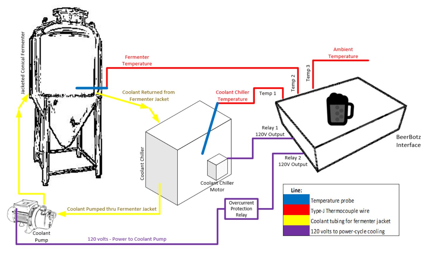
This case uses three of the thermocouple inputs, and both of the available relay outputs. Chilled
coolant (usually propylene glycol) is circulated through the "cooling jacket" on the fermenter.
This is done in order to maintain a target temperature in the interior of the fermenter. To make
this work, two temperatures need to be controlled. First, the coolant temperature is held as low
as possible without freezing up. There are charts that show the freezing temperatues of the
various ratios of propylene glycol-to-water mixtures. The colder the coolant, the more effective
it is at lowering the fermenter temperature.
Next, the interior fermenter temperature is maintained at the desired target by turning the coolant
flow through the jacket on/off.
This time, Temp 1 is sensing the coolant temperature, Temp 2 is sensing the interior fermenter
temperature, and Temp 3 senses the room temperature.
Relay 1 (keyed off of Temp 1) maintains the coolant temperature in the Coolant Chiller. This value
is set as low as possible without freezing with regard to the propylene glycol/water ratio (or
the specific properties of the coolant if a different coolant is used).
Relay 2 (keyed off of Temp 2) maintains the internal fermenter target temperature by cycling the
coolant pump on/off. The coolant pump circulates the chilled coolant into the fermenter jacket
and the warmed-up coolant from the jacket gets returned back into the Coolant Chiller. In this
case, the coolant pump is not directly connected to the Relay 2 output. This is because there are
potential problems with the electrical load that the coolant pump will provide when it starts up.
Because the coolant is so cold, this pump has the potential to draw a large amount of amperage
(inrush current) when it is first started. Also, pumps are inductive loads, which "dirties up"
the power line circuit that is suppling them. The placement of an Overcurrent Protection Relay between
the Relay 2 output and and coolant pump is necessary to isolate the BeerBotz interface from any
electrical problems arising from the operation of the coolant pump. Also, it is best to feed the
power to the coolant pump from a different electrical circuit than the one that is feeding the
BeerBotz interface.
Control Coolant and Fermenter Temperatures - with Gas Monitoring
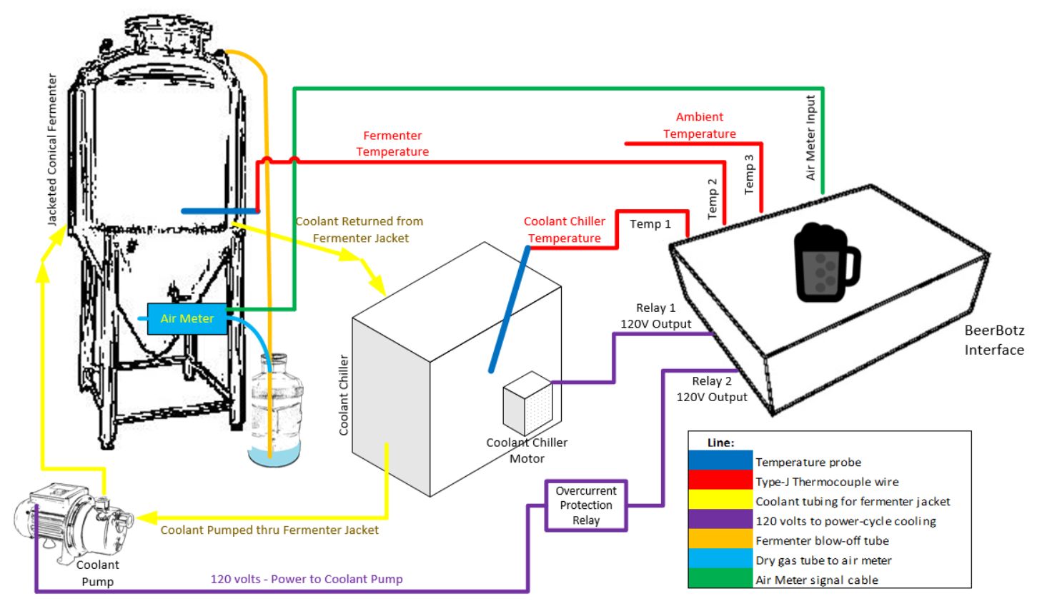
As the title suggests, this example is exactly like the previous one with the addition of
gas monitoring. Normally the gas produced at the top of the fermenter is directed with
a hose down into a plastic bucket with some water in it (for an air lock). If the fermentation
is still happening, you will observe bubbles in the water from the end of the hose. Also,
if the water is discolored, you know that the fermentation was once so vigorous that it blew
off some beer foam into the hose while it was bubbling.
To monitor the gas output with a sensor, we must first insure that no liquid water will
make it into the air meter. The Honeywell™ AWM series gas flow meters are
ruined if water ever passes through them. This is because there is a little eletrical element
inside these meters that fail upon contact with liquid.
To protect the air meter, the hose from the fermenter is directed to the bottom of a blow-off
bottle. There is a little water in this blow-off bottle to serve as an air lock. The top
of this bottle is sealed with a cap and the dry air pushing out of the bottle passes
through the air meter. Considering that we don't want to take a chance of
water pushing through the air meter, we can also adjust the fill level of the fermenter
so it is unlikely that we will get fermenting beer entrained in the blow-off hose (refer
to the Bubbler page).
The air meter is then connected to one of the air meter inputs on the BeerBotz interface. The
addition of the blow-off tube, blow-off bottle, air meter, and air meter signal cable are
the only differences between this example and the previous one.